Commercial Pellet Boilers, Case Study
We previously posted about the pellet boiler installation at our offices, which consists of two Froling P4 100 commercial pellet boilers. The prior post was made from the 30,000 foot perspective. This post dives a little deeper to also show key commercial pellet boiler installation components. From the fuel storage to the boilers we will show you pictures of each component to help understand how automatic pellet boiler systems work.
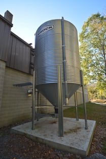
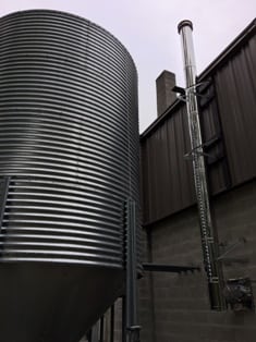
This is a 15 ton Galvanized silo used for wood pellet storage. The silo is 9 feet in diameter and stands nearly twenty feet tall. Each three foot high ring holds approximately 3 tons of fuel. The base funnel also holds approximately 3 tons. The silo is filled through a 4" pipe that the delivery truck attached to using a "cam-lock" connection (far right).
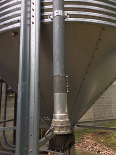
The base of the silo is split into two channels. Each channel allows pellets to flow through a slide gate into a base, which houses a special pellet pick-up device. The pellet pick-up is connected to two pipes. One pipe is under suction and the other pipe is blowing air. Both pipes are connected on the inside of the building to powerful vacuum motor that is standard equipment on the boiler. We chose to use welded steel pipe outdoors, as the vinyl tubing is not sunlight-stable (UV). In our particular installation we wanted to enter the wall of the building above human head height to avoid tripping hazards and to avoid having tubing in an area where people walk. Going underground would have been difficult in this case, but running tubing through PVC sleeves underground is often a nice solution. The steel tubing we used is 2" automotive exhaust pipe. Once inside the building, the steel pellet tubing is connected to the typical grounded, vinyl hose.


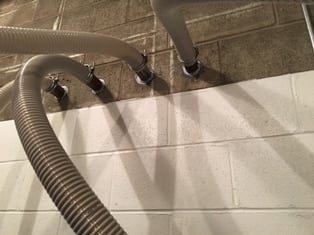
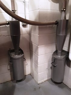
Inside the boiler room the pellets are conveyed through flexible, grounded, vinyl tubing. The return air pellet hoses are connected to dust cyclones, which strip out fine dust that might otherwise cause excessive long-term maintenance. The fines cyclones remove about 20 pounds of dust for every 10 tons of fuel used.

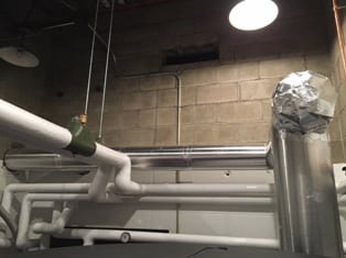
There is one chimney per boiler (stainless chimney added). The operating boiler is unable to influence the non-operating boiler through the vent connection and both boilers are assured proper draft. The long, stainless steel connector is carefully insulated (large silver pipe in photo at far right) to reduce the chance of condensation in the existing masonry chimney.
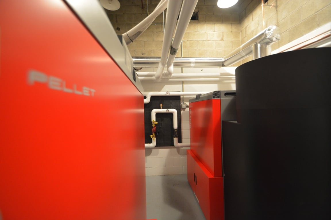
This is a photo of the two pellet Froling P4 100 pellet boilers in the boiler room. The room is only 11' x 12', which presented a challenge for fitting the boilers sensibly with regard to chimneys and future service. The layout wasn't obvious at first, but works very well as is.
The two boilers are connected together with a Froling cascade control. The control not only assures that each boiler has similar operating hours, but will also automatically start the non-operating boiler anytime the operating boiler can't meet heating needs due to a large demand or because it is out of service.
The two boilers heat about 20,000 square feet of cinder block walled, flat roof building with 12'-16' high ceilings. As evidenced by our heat meter, the two commercial pellet boilers never had to run at the same time in 2017/2018 to keep up with heating demand, which was a surprise to us. We surmise that the 1250 gallon buffer tank helped bridge short periods of high heat demand. The boilers burned 38 tons of wood pellets in 2017/2018 at a total cost of $9,272 ($244.00/ton).

There are other key features of this commercial pellet boiler installation that we believe are worth pointing out. All distribution pipes in the pellet boiler room and back to the distribution manifold are insulated. We want the heat delivered to where it is being called for and not being lost uncontrollably in the boiler room. The boilers are also protected from cold water return by three way mixing valves made by LK Armatur https://store.tarmusa.com/collections/lk-armatur-collection. Without these valves, it is likely that the boilers would form damaging condensation in the heat exchange tubes or in the chimney.


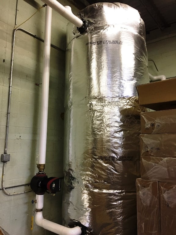
Both pellet boilers connect to a common supply and return pipe in the boiler room. The pipes exit the boiler room and go to a 1,250 gallon buffer tank located in an adjacent room. The buffer tank is 4' in diameter and 13' tall. We specified the tallest tank possible in order to enhance thermal stratification. From the buffer tank, a supply and return pipe run to the main building manifold. We placed a high efficiency Grundfos Magna 3 circulator on the return from distribution to the buffer tank. The circulator has a built-in return temperature sensor. We attached an additional sensor to the supply from the tank to the distribution manifold. The circulator has an internal differential control that maintains a constant 20 degree Fahrenheit difference between the supply and return pipes by varying its speed. This means that there are no circulator control wires from the main manifold to the pellet boiler plant. The Magna 3 responds to heating demands automatically. Below, there are photos of the buffer tank and of the circulator.

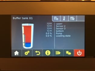
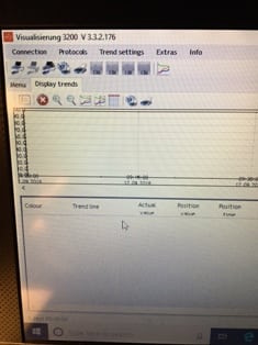
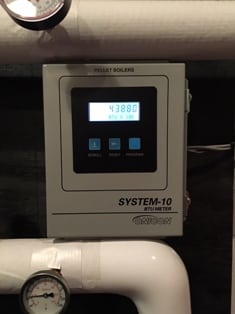
The last components to touch on are the electronics. The boilers themselves are equipped with touch screens, which allow for cloud monitoring via mobile app or via desk top computer. In the boiler room the boiler monitors several hundred inputs. One of the most important inputs is multiple sensor monitoring of the buffer tank. This can be seen at the image below/left. There is also a computer connected (below/center), which tracks and saves multiple boiler functions, which can be displayed as trends on a graph. While this computer is not necessary, it is a nice tool for fine tuning installations and operation parameters for cascaded commercial pellet boilers. Lastly, the boilers are monitored with a heat meter (below/right). The heat meter tracks the number of Megawatt hours of heat that are produced. Those Megawatts are sold on the open market as Thermal Renewable Energy Credits (T-RECs) for about $22.50 each. For more about T-RECS (New Hampshire and Massachusetts installations only) go to: http://inrsllc.com/WES%20INRS%20T%20REC%20Marketing%20Information%202-pager-1.pdf
